|
|
| OR
Gate |
|
|
An OR gate is a logic gate that has two or more inputs but only
one output. However, the output Y of an OR gates is LOW when all
inputs are LOW. The output Y of an OR gate is HIGH if any or
all the inputs are HIGH. |
|
|
It
is called OR gate because the output is high if any or all
the inputs are high. For the sane reason, an OR gate is sometimes
called "any or all gate". For example, consider a
2-input OR gate. The output y will be high if either or both
input are high.
|
|
 |
|
 |
|
Fig (a) |
|
Fig
(b) |
|
|
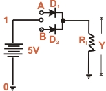
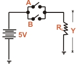
| OR gate Operation
: Fig (a) shown one way to build a 2-inputs OR gate while
Fig (b) shows its simplified schematic diagram. The input voltage
are labeled as A and B corresponds to 0 state (LOW level). The
positive terminal of the battery (+5V) corresponds to 1 state
HIGH level). There are only four input-output possibilities.
|
|
(I) When both A and B are connected to ground, both diodes
are non-conducting. Hence the out put voltage is ideally zero
(lo voltage). In terms of binary, when A = 0 and B = 0, then
Y = 0 as shows in the truth table.
(II) When A is connected to ground and B connected to the
positive terminal of the battery, diode D2 is
forward biased and diode D1 is non-conducting.
Therefore diode D2 conducts and the output voltage
is ideally +5V. In terms of binary, When A = 0 and B = 1,then
Y = 1 as shows in the truth
table.
(III) When both A and B are
connected to the positive terminal of the battery and B
to the ground, diode D1 is on and diode D2
is off. Again the output voltage is +5V. In binary terms
when A = 1 and B = 0 then Y = 1 as shows in the truth table.
(IV) When both A and B are connected to the positive terminal
of the battery, both diodes are on. Since the diodes are
in parallel, the output voltage is +5V. In binary terms,
when A = 1 and B = 1 ,then Y = 1 as shows in the truth table.
|
|
| A |
B |
Y |
|
0 |
0 |
0 |
0 |
1 |
1 |
1 |
0 |
1 |
|
1 |
1 |
1 |
|
Truth
Table |
|
|
IT is clear from the truth table that for OR gate, the output
is high if any or all of the inputs are high. The only way to
get a low output is by having all inputs low. Fig (C) shows
the logical symbol of OR gate. Note that the symbol has curved
line at the input |
|
|
|
| Fig
(c) |
|
Boolean Expression
: The algebra used to symbolically describe logic function
is called Boolean algebra. The "+" sign in Boolean
algebra refers to the logical OR function. The Boolean
expression
for OR function is
A + B = Y where "+" is OR symbol
|
|
|
A
+ B |
Y |
|
0 +
0 |
0 |
0 +
1 |
1 |
1 +
0 |
1 |
| 1
+ 1 |
1 |
|
| Adjoining table |
|
The
adjoining table shows possibilities for the inputs. According
to this table, when 0 is OR with 0 , the result equals 0.
Also, any variable OR with 1 equals 1.The OR function can be
summed up as under:
0 OR with 0 equals 0
0 OR with 1 equals 1
1 OR with 1 equals 1
|